- Programming for Arduino
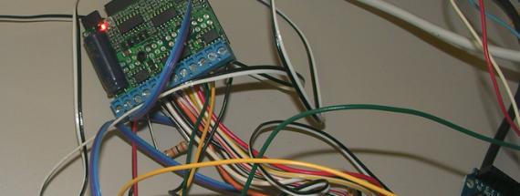
To control the motors, I used two Geckodrive G25I drives and one Diecimila arduino board. Below you will find the code for the arduino.
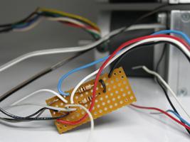
1) Solder a 1000 ohm resistor to each switch. For the upper box, connect the switch to digital pin 3 on the arduino board and for the bottom box, to digital pin 2. Basically, you need one side of the switch to go to ground, the other to a resistor and ground it to the arduino board as well as to the selected pin.
Pan limit switch: pin2(arduino)
Tilt limit switch: pin3(arduino)
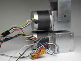
2) Then, using a multimeter, find the two pairs of wires on your stepper motor. For this type of motor, the pairs are blue/white and yellow/green. Don't use the red and black wires. For more information, please see the data sheets on motors and drives. Of course, this will vary if you are using others motors and drives. So you should look at the data sheets carefully!
3) On the drive board, connect the
- connector 1 to ground and 2 to 12VDC from a power supply
- connectors 3 and 4 to a 1000 ohm resistor
- connector 5 to the motor's blue wire, 6 to the white wire, 7 to yellow, 8 to green
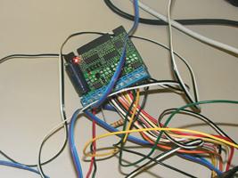
- connector 9 (which is the direction) and 10 (the step) to the arduino selected digital pins **
* For the upper box: the tilt motor is controlled via digital pin 10 for the (direction) and digital pin 8 for the (step). The tilt direction HIGH(1) is ''back'' (i.e. towards the limit switch).
* For the bottom box: the pan motor is controlled via digital pin 7 for the (direction) and digital pin 6 for the (step). The pan direction LOW(0) is ''left'' (if standing behind the p/t), and this is the direction for the limit switch.
- connector 11 - (disable)
- connector 12 to ground on your arduino.
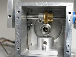
4) Now, inside your gearboxes, unscrew the small arms and push them away from the limit switch, so you can test the code. If you are using the code below, you want to make sure that the initial programmed direction is fine. First , the upper gearbox should go right and the lower gearbox left. The switches should show a numeric value of 1 when activated and 0 when not activated. If that is not the case, make sure to change the code below. Of course, you can write your own code to match your connections on the boards. Turn the motor to its limit manually, then screw the small arm so the switch is activated. And Voilà! It's done! Now you can work with the code!
note: > coming soon more information on how to create a great smooth routine for your pan tilt.
Video: Initializing the position of the Pan Tilt using the arduino code below.
Arduino Code - pt_simple.zip
G251 GECKODRIVE Microstep Drive : http://www.geckodrive.com/upload/G251%20MANUAL.pdf
SparkFun Easydriver : http://www.sparkfun.com/commerce/product_info.php?products_id=9402
Stepper motors: TL57ST56-02B2 http://www.interinar.com/tl57st56-02b2.html
NEMA 23 - Size 57mm, 1.8deg 6-Wire Stepper Motor
Intro | Kit Requirements | STEP 01 | STEP 02 | STEP 03 | STEP 04 | STEP 05 | STEP 06 | STEP 07 | STEP 08 | STEP 09 | STEP 10