- Basic 2D Drawings in RHINOCEROS
note: Rhinoceros is a terrific modeling software for designers. You can draw high precision 3D or 2D parts and export your file as STL for 3D printing or DXF for any AutoCAD, solid work, or bobcat software. You can also use Rhino Cam with your Rhino file to translate it directly to G-Code. Which means that you can use any CNC machine with your Rhino drawings. If you are just beginning with Rhino and Rhino Cam, I highly recommend that you go through all the tutorials and video. (DVD available at Fremont Lab). Also, you should visit the Rhino website for extra tips and examples.
* RHINO DEMO VIDEO under construction
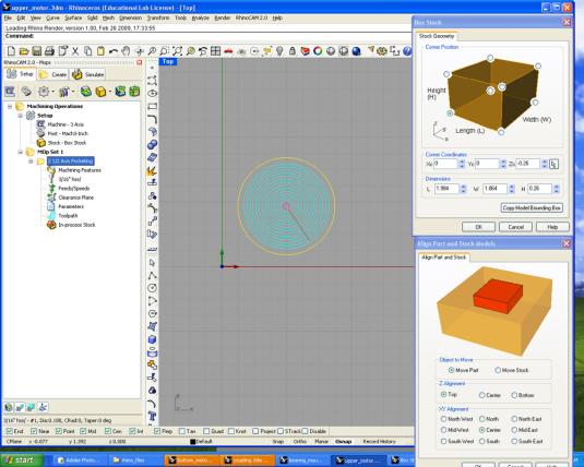
note: In Rhino Cam, make sure that your stock is well positioned and that the dimensions are exactly equivalent to your aluminum part. Also, take your time to go through each menu before "posting all" as G-Codes.
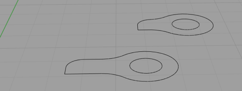
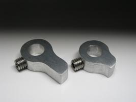
- Small arms for the switches (2 drawings)
Create your own design!
Their function is to activate the switches that will reset the position of the pan tilt system. The small arms need to be fixed to the shaft. You can add a setscrew on the side to lock it in place on the shaft (see the video in Step 6). In Rhino, draw 2 circles, one with a diameter of 0.5” and the other 0.25”, and create the shape you want to activate the switch. (See drawing below)
For the top box, the dimensions should be maximum: 0.65” x 0.5” x 0.25 “
For the bottom: 0.87” x 0.5” x 0.25 “
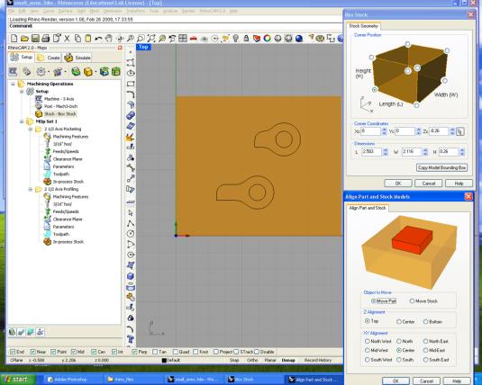
When your drawings are done, open Rhino Cam. Set your stock dimension exactly to the size of your aluminum part.Then create two actions: pocketing for the inside of the small circle and profiling for the outside of your shape. Go through the entire menu for each action. Then play the simulation and, if everything is okay, “post all” by clicking the left side of the mouse. Look at your G-Code and check your XYZ axis. You are now ready to bring your codes to the CNC Mill computer. tip: Add a few bridges to your parts in Rhino Cam so that the parts don’t fall down before the end of the final cutting pass. For more information, look at the tutorials on how to use Rhino Cam as well as the special tutorial on Rhino Cam for the Fremont CNC MILL at wikipedia Fremont.
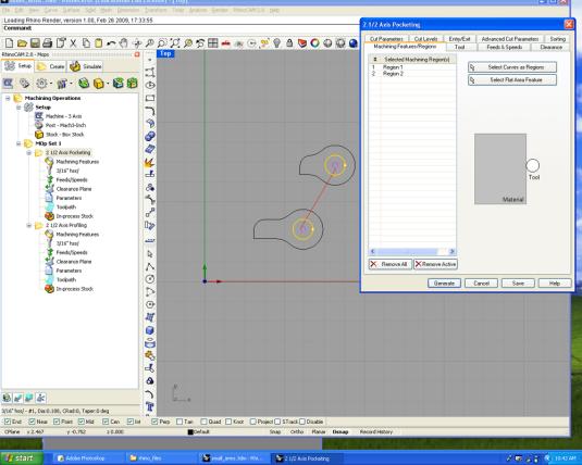
POCKETING_REGION 1
2) Select both circles as region 1 and your shapes as region 2.
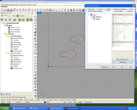
3) Use a 3/16" cutter mill.
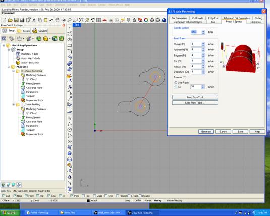
4) 1200 RPM for the speed of the spindle and 4 in/min for all the feed rates. For the transfer feed, use 10 in/min.
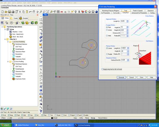
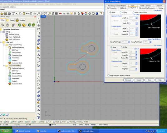
5) We will need a path engage motion and a linear retract motion. For more information, follow the Rhino Cam Tutorial, available at Fremont DX Lab.
6) Nothing to select here
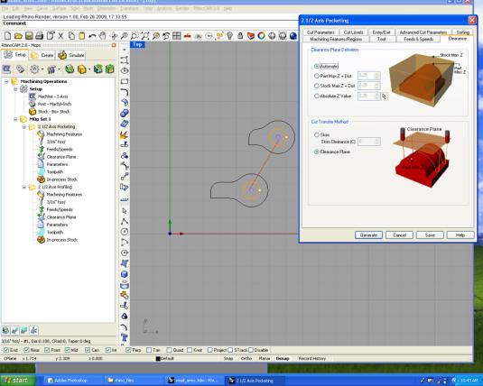
7) Select an automatic clearance plane definition and a clearance plane in the cut transfer method.
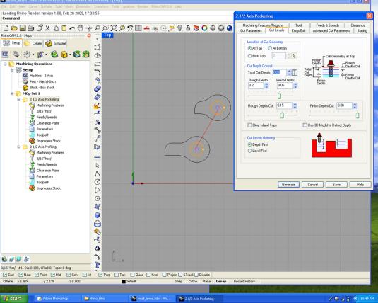
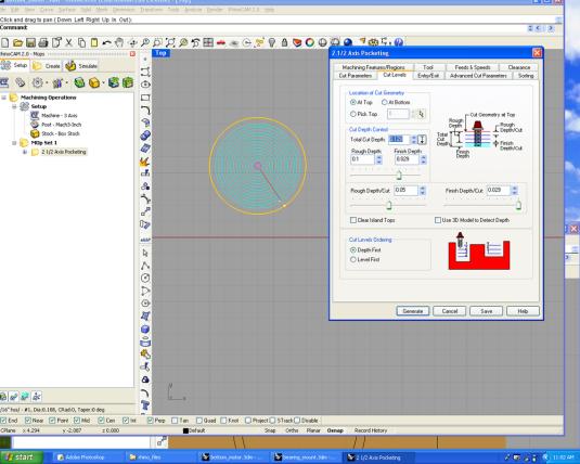
8) Since you want the holes to go all the way through, select the total cut depth at 0.26". You want this to be slightly more than the actual aluminum width. Also, you want more rough cuts than finish cut.
In the example here, you have 0.2" of rough depth and 0.06" of finish depth. You should change the rough depth/cut to 0.1, which will means a total of 2 rough cuts and then 0.06" finish depth/cut = 1 finish cut.
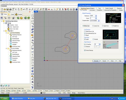
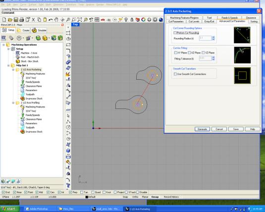
9) To have a nice finish, attempt this with at least 0.001" of tolerance and 25% tool diameter steep distance. Also, select inside as the start point.
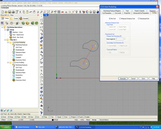
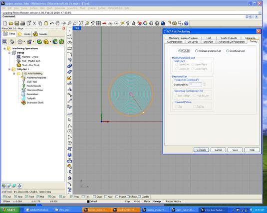
10) No sort needed
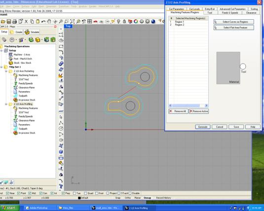
PROFILING_ REGION 2
1) Select region 2, your shapes.
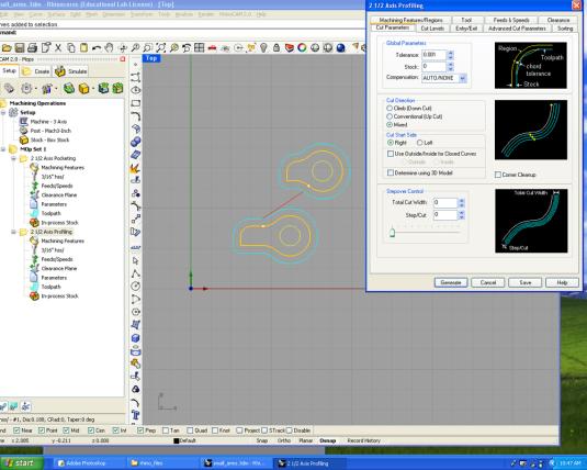
2) Set the tolerance to 0.001".

3) Here again, you want the profiling action to go all the way through, so set the total cut depth at 0.26". Double check all your rough and finish depths and cuts.
4) Nothing to select here
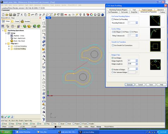
5) Here, you can add some bridges to make sure that your parts won't fall while being cut. Since these parts are quite small, you don't need more than 2 bridges and they can be really small.
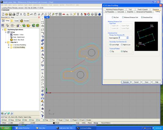
6) Here you need a low to high sorting with a zigzag pattern.
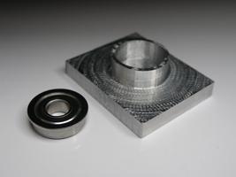
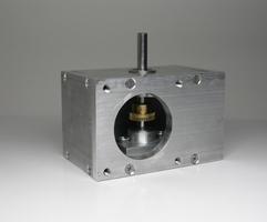
Bearing mount for the bottom box (1x)
In the middle of your stock, draw two circles, one measuring 0.624" for the bearing and the other 0.7" as well as a rectangle the size of your aluminum part.
In Rhino Cam, you need two actions: pocketing the inside of the small circle and facing the outside of the larger circle.(See images below)
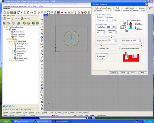
POCKETING_Region 1
Smaller circle selected
1) For the bearings mount, you don't want the hole (pocketing) to go all way through. Double check the cut/depth. You will need to insert your bearings in this pocket circle.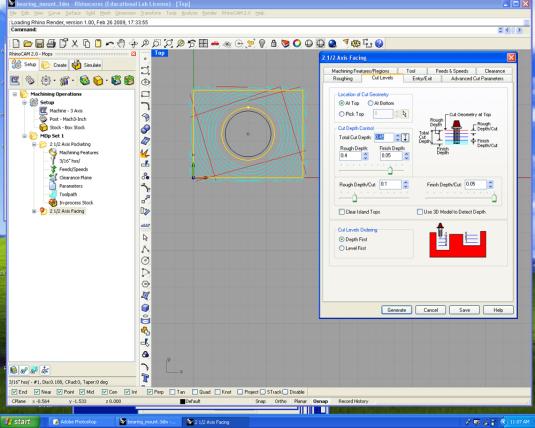
FACING_Region 2
Select the larger circle and the rectangle
2) You don't want to face all way through. Double check the cut/depth.
Coupling for the upper box (1x)
You need a rectangle of the size of your aluminum part and in the middle, draw two circles, one with a diameter of 0.25" for your shaft and the other 0.75". This is to fix the upper gearbox to the bottom one.
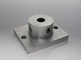
In Rhino Cam, you will need two actions; pocketing the inside of the small circle all the way through and facing the outside of the larger circle. (See images below)
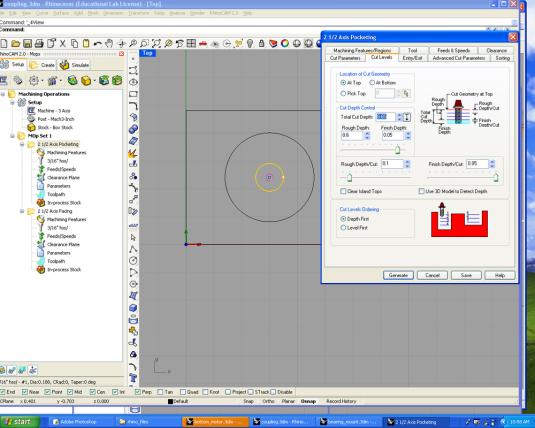
POCKETING_Region 1
Smaller circle selected
1) For the coupling, you want the hole (pocketing) to go all way through. Double check the cut/depth. Make sure it is slightly deeper than the width of your aluminum part.
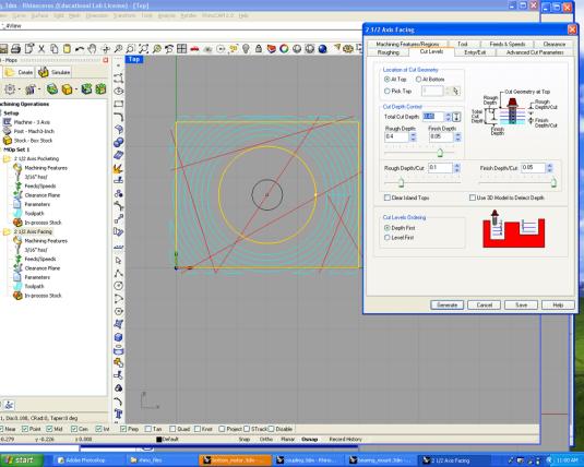
FACING_Region 2
Select the larger circle and rectangle.
2) Double check the cut/depth.
- Motor plates (2x)
For the upper box, draw a 2.25" diameter circle in the middle of your stock. For the bottom box, draw the circle at 2” from the left.
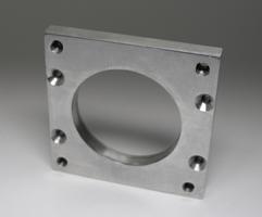
In Rhino Cam, you will need one action: pocketing the inside of the circle all the way through.
POCKETING_Region 1
Select the circle.
1) The hole (pocketing) needs to go all way though. Double check the cut/depth. Make sure it is slightly deeper than the width of your aluminum part.
2) No sort needed
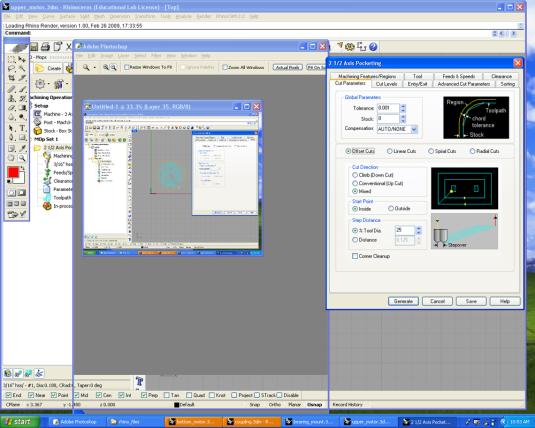
3) Don't forget to change the tolerance to 0.001" and 25% of the Tool diameter.
4) Make sure to align your part in the top center of your stock for the upper box and 2" from the left for the bottom box.
Tip: For the bottom box, you can draw a rectangle the size of your aluminum part and place the circle in position. Then, you can move both the rectangle/circle in the center of your stock. Make sure your stock is the exact dimension of your aluminum part.
- Hole for the bearings in the upper box (1x)
Draw a 0.374” diameter circle at 0.4” from the top of your stock and 0.875” and 1” from the side.
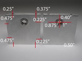
In Rhino Cam, you need one action: drill or pocketing the inside of the circle all the way through. If you want to go with pocketing (much more precise) well, make sure to use a smaller cutter mill and change it in the Tool menu. Note: you can also do these holes on the drill press (Less precise but possible!)
- Hole for the bearing in the bottom box (1x)
Draw a 0.624” diameter circle at 1.5” from both sides and from 0.875" and 1" from the top/bottom.
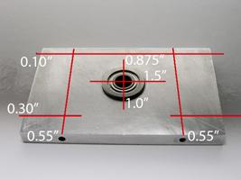
In Rhino Cam, you need one action: drill or pocketing the inside of the circle all the way through. If you want to go with pocketing, it will be more precise. Well, in this case, make sure to use a smaller cutter mill and change it in the Tool menu. Note: you can also do these holes on the drill press (Less precise, but possible!)
Intro | Kit Requirements | STEP 01 | STEP 02 | STEP 03 | STEP 04 | STEP 05 | STEP 06 | STEP 07 | STEP 08 | STEP 09 | STEP 10