- Run your G-Codes on the CNC Mill
(See the video below)
Make sure to go through the wiki CNC Mill Tutorial and get Fremont Lab Authorization before using the CNC Mill.
1. Install your stock in the mill vise properly so the mill cutter doesn't cut the vise while running your program.
2. Next, with the edge-finder, set the X and Y-axis to 0 at the bottom left corner. Don’t forget to subtract half the size of the edge-finder. When the kickoff of the edge-finder begins, set the coordinates menu X-axis to –0.1 and Y-axis to -0.1.
3. Take away the edge-finder then put a 3/16" end mill cutter in the chuck. Make the bit touch the top of the stock by moving it manually with the right handle, then set your Z-axis to 0.
4. Go to the INPUT menu command line and write Z1.5 to make the chuck move up to 1.5". Then set your Z1.5 to 0 in the coordinates menu. This will allow an air test of your G-Code program.
5. Open your G-Code in the software, then click start your program. While testing, look at both your monitor and the machine, double check that the mill cutter isn’t touching the mill vise and that all your G-Codes are running properly. (Feed rates…etc).
6. If everything is fine, go back to the INPUT menu command line and enter Z0. The chuck will move back to Z0. Then in the coordinates menu, write down Z1.5 and click enter.
7. Turn on the spindle to 1200.
8. Run your program occasionally adding cutting fluid and spray air on the metal swafts.
9. Finally, clean the machine in 4 steps. 1) Take away the cutter and collet, close the machine, unplug it, 2) with the compressed air gun, blow away all the metal dust on the machine, the side of the computer cabinet and the tools on the wall 3) Then with the vacuum and broom clean the entire floor. 4) Place the rags back on the vise.
note: When all your parts are ready, sand them and verify the diameter of the holes with the caliper. You may have to sand the holes until your bearings and shaft fit perfectly. For the bearings, you want them to fit tightly in the holes. However, don’t install them yet!
Video on how to establish your X-Y-Z axis to 0.
REQUIRED PARTS
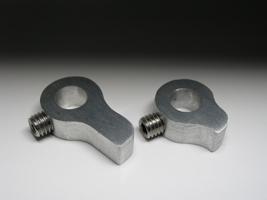
- Small arms
When you are done machining the small arms on the CNC Mill, make sure that your shaft fits in the hole perfectly. Because of the some lack of accuracy, it is possible that you may need to drill the hole with a 1/4" drill bit afterward. Then, using a metal handsaw, cut the bridges and sand them carefully. You will also need a threaded hole to insert a setscrew. This will fix them in place on the shaft later on.
Rhino file
G-Code
Photo: Machining the small arms on the CNC Mill at DX Fremont Lab
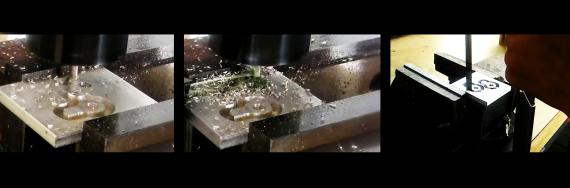
Video: Machining the small arms on the CNC Mill at DX Fremont Lab
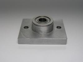
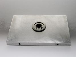
- Bearing mount
When you are done machining the bearing mount on the CNC Mill, make sure that the hole fits the measurement of your bearing. Because of some lack of accuracy, it is possible that you may need to sand it slightly. caution: If your hole is too small, the bearing may fit but you might damage it. Your hole needs to be the right size so the bearing can be pressed in easily. This bearing is small and therefore very fragile. When the measurements fit the requirements, insert the bearing in your part with a soft hammer or a press fit. Also, you can add some Loctite - 620 Bearing Mount while you insert them in place.
You also need two holes to mount this part on the bottom of the bottom box. I used #10-32 screws for this.

Rhino file
G-Code
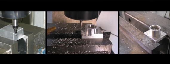
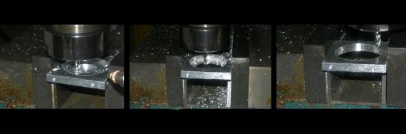
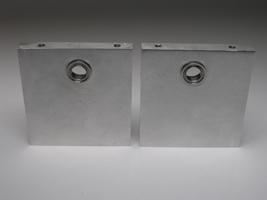
Photo: Machining the bearing mount on the CNC Mill at DX Fremont Lab
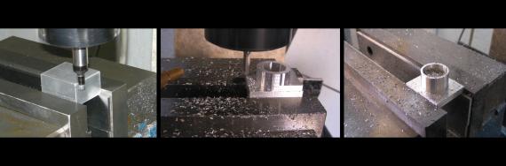
Video: Machining the bearing mount on the CNC Mill at DX Fremont Lab
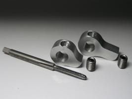
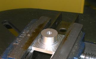
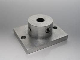
- Coupling
When you are done machining the coupling on the CNC Mill, make sure that your shaft fits perfectly in the hole. Again, because of some lack of accuracy, it is possible that you may need to drill the hole with a 1/4" drill bit afterward. You need two threaded holes to insert setscrews. This will fix the shaft in place later on. You also need two holes to mount this part on the bottom of the upper box. I used #10-32 screws for this.
Rhino file
G-Code
Photo: Machining the shaft coupling on the CNC Mill at DX Fremont Lab
Video: Machining the shaft coupling on the CNC MIll at DX Fremont Lab
- Motor plates
For the motor plates, you can always make the holes larger than needed, so you can move your motor slightly if needed. Personally, I prefer to make the holes to fit the size of the motor, so when I mount the motors and I know they are in the perfect location. Of course, this option needs a lot of precision and meticulous work.

Rhino file
G-Code
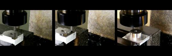
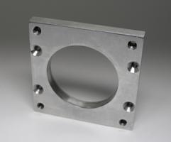
Photo: Machining the motor plates on the CNC Mill at DX Fremont Lab
Video: Machining the motor plates on the CNC Mill at DX Fremont Lab
- Holes for the bearings in the upper box (**)
For these two holes, I used a 3/8" drill bit, but you can do them by programming the CNC Mill to "pocket" a 0.3740” hole using a smaller cutter mill. When you are done machining, make sure that the holes fit the measurement of your bearing. It is quite possible that you might need to sand them afterwards. Don't install your bearings yet. caution: If your holes are too small, the bearings may fit but you might damage them. Your holes need to be the right size so the bearings can be pressed in easily. The bearings are really small and therefore very fragile.
- Hole for the bearing in the bottom box (**)
Intro | Kit Requirements | STEP 01 | STEP 02 | STEP 03 | STEP 04 | STEP 05 | STEP 06 | STEP 07 | STEP 08 | STEP 09 | STEP 10