- Mark, drill, and tap.
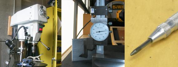
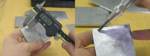
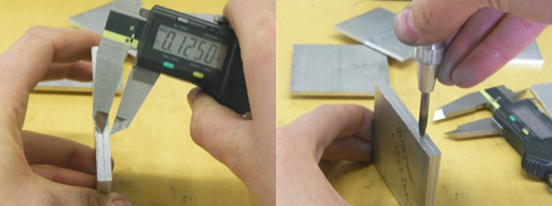
Now, you need to mark all the parts using the caliper or the measuring tool on the layout table. Then with the center punch, mark the location of your holes. This step needs a lot of precision!
tip: make sure that your punch point is sharp enough. If needed, sand it or change it. Also engrave numbers on each side of the box so it can always be assembled in the same order.
info on tap and die: http://en.wikipedia.org/wiki/Tap_and_die.
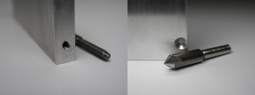
Basically you have to make a few threaded and countersunk holes.
Tap and drill bits needed: tap bit #4-40 with drill bit #43, tap bit #6-32 with drill bit #36
tap bit #10-32 with drill bit #21 and 1/4" x 82 countersink bit.
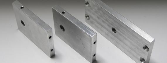
Upper box:
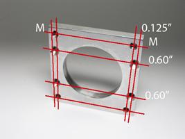
Motor plate (2.25" x 2.25" x 0.25"):
You need 4 threaded holes to mount your motor (M). Mark the location of the holes with the center punch and drill with the #21 bit, tap your hole with a #10-32 tap bit. You will also need 4 countersunk holes to assemble the plate with the others. Trace a line at 0.125" on the two sides and with the punch, mark at 0.6" at each extremity, drill a hole with a #36 bit, and then with the countersink bit, drill the v shape for the screw’s head.
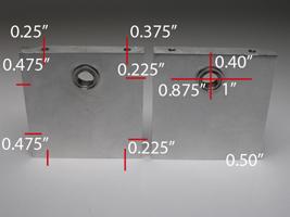
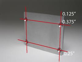
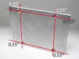
Side plates (1.875" x 2" x 0.25"):
You need a total of 8 threaded holes on the edges of both side plates. Mark the location of the holes as shown below with the center punch and then, on the drill press, drill using a #43 bit and tap the hole for a #4-40 screw. The hole should be more deeper than the screw length. On each side plate, you will also need a hole to insert a small bearing, which can be done on the CNC Mill. High precision needed! note: When you tap a hole, make sure to add a bit of cutting oil, or grease to your tap bit. Turn it very slowly, forward 360 degrees and then, backward 90 degrees. tip: a 4-40 tap is really fragile. Make sure to hold it straight and turn it very carefully.
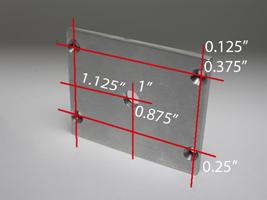
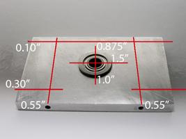
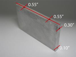
Bottom plate (1.875" x 2.25" x 0.125"):
On the bottom of your box, you will need 4 countersunk holes as shown below, as well as a 1/4" hole for the shaft. The shaft's hole needs to be 1" from the top/bottom as well as 1.125" and 0.875" from the side.
Top plate (1.875" x 2.25" x 0.125"):
4 countersunk holes as shown below.
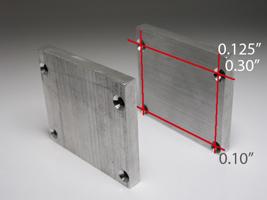
Front plate (2.25" x 2.25" x 0.125"):
Bottom box:
Motor plate (3.5" x 2.25" x 0.25"):
4 #10-32 threaded holes to mount your motor (M) as well as 4 countersunk holes to assemble the plate with the others. Trace a line at 0.125" on the two sides and with the punch, mark at 0.8" at each extremity, drill a hole with a #36 bit, and then with the countersink bit, drill the v shape for the screw’s head.

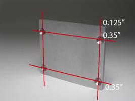
Side plates (2" x 2.25" x 0.25"):
4 countersunk holes
Top plate (3" x 1.875" x 0.25"):
8 #4-40 threaded holes, 2 per edge, as well as a hole to insert a bearing, which will be done later on the CNC Mill.
Bottom plate (3" x 1.875" x 0.25"):
8 #4-40 threaded holes, 2 per edge as fallows.
Front plate (3" x 2.25" x 0.125"):
4 countersunk holes
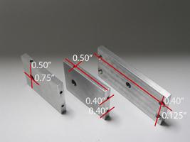
Mounting arm:
Side plates (2" x 1.5" x 0.25") and Top plate (3.25" x 1.5" x 0.25"):
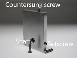
On both side plates, you will need a 1/4" hole for the shaft at 0.50" from the bottom as well as 2 #4-40 threaded holes on the top edge to assemble the mounting arm and one #6-32 threaded hole on both side edges at 0.50" from the bottom. For these two holes you will need a setscrew to fix the shaft in place. Then on the top plate, you will need 4 countersunk holes and one in the middle for mounting your device.
Video on how to tap your holes:
Intro | Kit Requirements | STEP 01 | STEP 02 | STEP 03 | STEP 04 | STEP 05 | STEP 06 | STEP 07 | STEP 08 | STEP 09 | STEP 10