
Overview
OpenBCI stands for open-source brain-computer interface (BCI). The OpenBCI Board is a versatile and affordable bio-sensing microcontroller that can be used to sample electrical brain activity (EEG), muscle activity (EMG), heart rate (EKG), and more. It is compatible with almost any type of electrode and is supported by an ever-growing, open-source framework of signal processing tools & applications.
The full steps for setting up the system is here.
Simple Hardware Setup for the Art and Brain Class
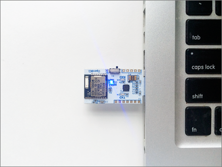
1.Plug in your OpenBCI USB Dongle
Plug this in (facing upwards!) and you should see a blue LED light up.
Note: make sure your USB Dongle is switched to GPIO 6 and not RESET. The switch should be set closer to your computer as seen in the picture to the right.
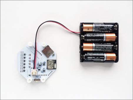
2. Plug in your 6V AA batter pack (with batteries)
Both the 8bit board and the 32 bit boards have specific input voltage ranges. These input voltage ranges can be found on the back-side of the board, next to the power supply. BE VERY CAREFUL to not supply your board with voltages above these ranges, or else you will damage your board’s power supply. For this reason, we recommend that you always use the battery pack that came with your OpenBCI kit. There’s a good reason we put this notice in here twice!
3. Switch your OpenBCI board to PC (not OFF or BLE)
Make sure to move the small switch on the right side of the board from “OFF” to “PC”. As soon as you do, you should see a blue LED blink 3 times (if you’re using the 8bit board; the 32bit version doesn’t blink). If you don’t, press the reset button just to the left of the switch. If the LED still does not blink 3 times, make sure you have full battery. If you’re sure your batteries are fully charged, consult thehardware section of our Forum.
Note: it’s important to plug in your Dongle before you turn on your OpenBCI board. Sometimes, if the data stream seems broken, you may need to unplug your USB Dongle and power down your OpenBCI board. Make sure to plug your USB Dongle in first, then power up your board afterwards.
4. Connect your electrodes to OpenBCI
At this moment, we are only using the lower row pins on the openBCI board.
Forhead eletrode ---> GND wire ---> AGND lower row pin on the openBCI board
Earlob eletrode ---> RE wire (reference) ---> SRB lower row pin on the openBCI board
Depending on what kind of brain signal you want to detect, we use different eletrodes on the EEG cap. And they are labed on each of the wire that is used to connect with the openBCI board.
For example, we want to detect the Posterior Dominant Rhythm. The eletrodes are O1 AND O2 for detecting the Rhythm. You will want to connect the wires that are taged as O1 and O2 with the openBCI board lower row pins. You will want to identify the pin name on the board with the channel numbers in the openBCI app. If the O1 is connected with N8P pin on the board, it should show up signal on the 8th channel of the openBCI app.
For more software setup, please visit UW canvas page, Art and Brain class 490.