This tutorial works through the AC Dimmer circuit as fabricated in Winter 2013. Details of that circuit are here: AC Dimmer Circuit.
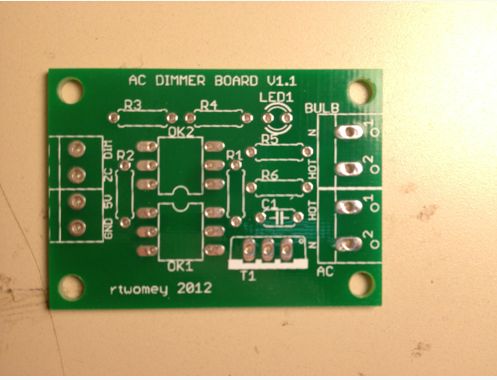
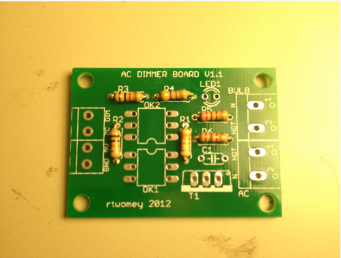
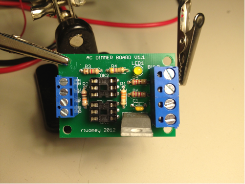
You are going to build this:

Populating the Board
- Grab your PCB. We are going to populate the board from the bottom up, shortest to tallest components.
- Grab your parts. The parts list is here acdimmer_parts.txt
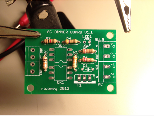
- Start with the resistors. Get these from the resistor bin.
- 33K (R1)
- 10K (R2)
- 1K (R3)
- 470 (R4)
- 180 (R5)
- 2.4K (R6)
- NOTE: if a value is not available (180 or 2.4K) consult with the engineer, or pick something close--220 and 2.7K, in this case.
- Insert the resistors into the board in the appropriately labelled spot. You may want to bend the legs slightly to hold them in place.
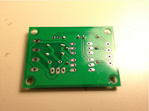
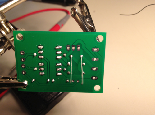
- Flip the board over and solder each resistor in place. As you solder a resistor, straighten the legs back out. This will give them each solder pad a straight, centered solder blob.
- Make sure that the resistor stays flush to the top side of the board! If one has slipped out, you can reheat the solder pad and push it into place, letting the solder harden again
- Solder joints should be symmetric, conical, and have a shiny finish. You do not want a big ball of solder.
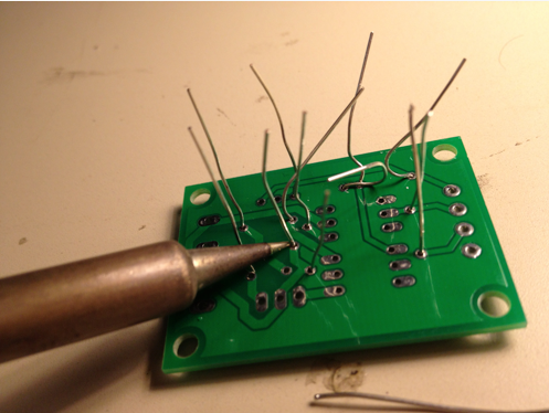
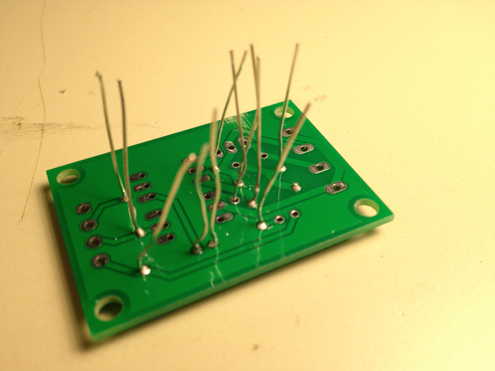
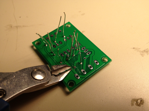
- Clip the resistor leads near the board, at the top of the solder joint.
- You can do this as you work your way through soldering the resistors, to free up space, or do it all at the end.
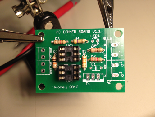
- Next, solder the 6-pin DIP sockets in place. These are the next tallest components.
- Make sure that the notch in the DIP socket aligns with the notch in the silkscreen image. This is how you are ensure the component is oriented correctly in the socket.

- Find a way to secure them flush to the board while you solder on the back. I balance the board on top of the sockets and make sure the legs are all sticking through, and apply a little downward force to keep the sockets flush.
- Solder one corner of the socket, then the opposite corner. This secures the socket.

- If the socket is not flush. Heat the appropriate corner and push to make it flush, then let the solder harden again.
- When you are satisfied with the flush-mounted DIP socket. Solder the remaining 4 pins on each socket

- Solder the capacitor and trim leads.
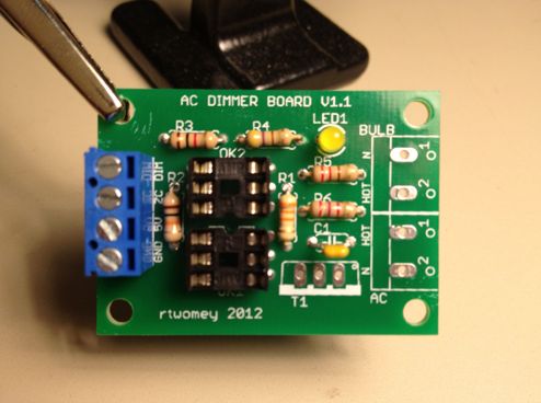
- Solder the LED and trim leads.
- IMPORTANT: the boards do not have any polarity markings on the silk-screen layer. Make sure you insert the LED properly. Looking at the photo below, the negative side of the LED should be to the left. Consult the schematic and board layout images if you are confused.

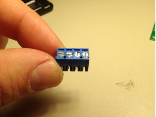
- Solder the short (3.5mm) screw terminals to the board.
- Snap the two screw terminals together. They have a special slot system. You can figure it out.
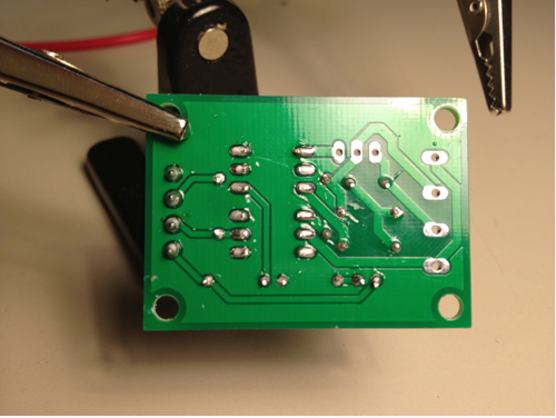
- Solder the terminals to the back of the board.

- Solder the tall (5mm) screw terminals to the board.

- Solder the TRIAC in place and trim the leads. Notice the orientation of the Triac!
- This design can use either the TIC201 2.5A Triac or Q40008L4 8A Triac we stock in the lab. They have the same package. If you have your own with a different power rating you can swap it in.
- Insert the two optocouplers into the DIP sockets.
- Notice which one is which. The H11AA1 is above, and the MOC3020 is below.
- Notice the orientation of each optocoupler. The MOC3020 has the notch upwards. The H11AA1 has the notch downwards.
- The pins may not quite fit into the socket. Bend the them slightly in with your fingers.

- Voilá. Time to test and verify.
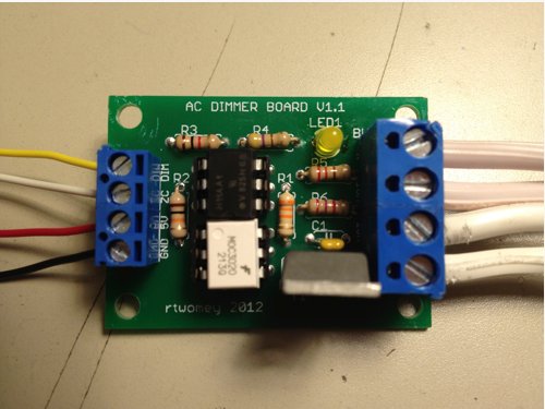
Test and Verify a Soldered Circuit
- Attach hookup wire to GND, 5V, ZC (Zero Cross), and DIM (Dimming) terminals.
- Connect GND and 5V to the Arduino.
- Momentarily connect DIM to 5V. You should see the dimming indicator LED light is working.
- Upload