Overview
Simple AC Dimmer circuit for incandescent bulbs. 128 levels of brightness. Parts are relatively cheap!
How it Works
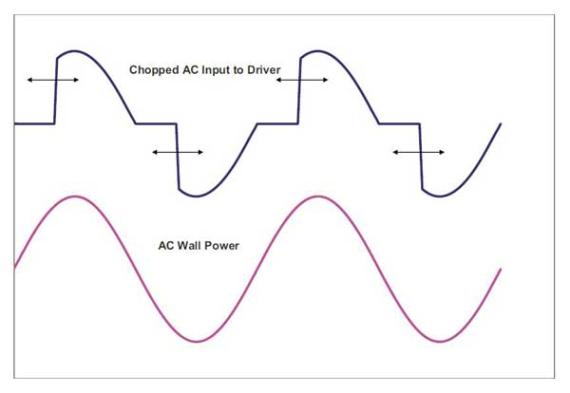
- This is an AC Chopping Circuit.
- The dim level sets where the AC waveform gets chopped on. More of the cycle makes the bulb brighter, less is dimmer.
- (from digikey http://www.digikey.com/ca/en/techzone/lighting/resources/articles/Retrofit-LED-Bulbs-and-Drivers.html)
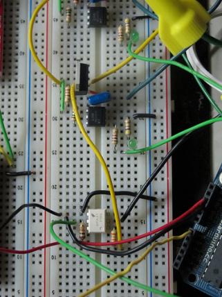
Photo
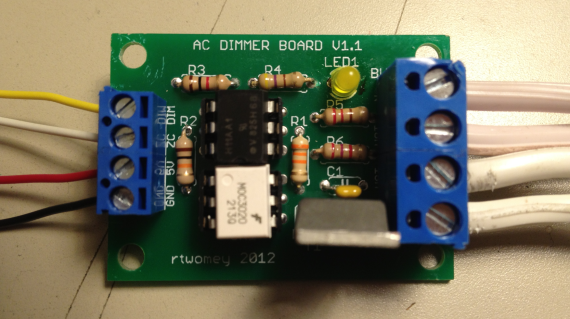
- Digital Signals. The four signals on the left. They are labelled on the board.
- Yellow: light dimming signal, comes from Arduino digital pin 11.
- White: zero-cross signal, goes to Arduino digital pin 2 in.
- Red: arduino +5V supply.
- Black: arduino GND.
- The LED on board should dim or fade along with the AC light source. Fading will not work until AC power is connected, it depends on the zero-cross info from the H11AA1 chip.
- AC Signals. The four white cords on the right. The bottom two cables on the right are the AC plug. The top two are the Bulb. These are labelled on the board, but are partially covered by the large screw terminals.
- Bottom is AC Power - Neutral.
- Bottom Middle is AC Power - Hot.
- Top Middle is Bulb - Hot.
- Top is Bulb - Neutral.
- NOTE: For help identifying Hot and Neutral on lamp cord, look here.
Code
- example with slow on/off fade: acdimmer_sleeping.zip
- example with potentiometer control: acdimmer_pot.zip
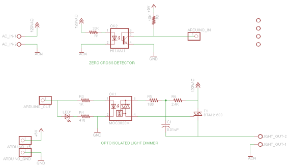
Schematic
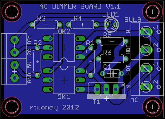
Board Layout
PCB Files
Parts
- acdimmer_parts.txt
- 33K
- 10K
- 1K
- 470
- 180
- 2.4K
- 0.01uF capacitor
- generic LED
- H11AA1 - Optocoupler AC Input 1 Channel http://www.jameco.com/webapp/wcs/stores/servlet/Product_10001_10001_18825_-1
- MOC3020 - DIP-6 OPTOISOLATOR Triac Driver http://www.jameco.com/webapp/wcs/stores/servlet/Product_10001_10001_277780_-1
- BTA12-600 - 600 V, 12 A, SNUBBERLESS TRIAC http://www.jameco.com/webapp/wcs/stores/servlet/Product_10001_10001_2034010_-1
From a PCB
If you had some of these manufactured, then you'll want to build the PCB. See our tutorial on Populating a Fabricated PCB.
On a Breadboard
CLICK THROUGH FOR ANNOTATED FLICKR VERSION
Notes
- Make sure your Triac (T1, BTA12-600) is rated at high enough current for the device you are controlling. The product linked above is rated at 12Amps RMS. That's a lot of current!
- Alternative TRIACs with different power ratings:
- TIC201M Thyristor TRIAC 600 Volt 12A 3-Pin (2.5A RMS) -http://www.jameco.com/webapp/wcs/stores/servlet/Product_10001_10001_1165690_-1
- Q4008L4 TRIAC 400V (8.0A RMS) - http://www.jameco.com/webapp/wcs/stores/servlet/Product_10001_10001_160207_-1
- Q6008L5 TRIAC 600V (8.0A RMS) - http://www.jameco.com/webapp/wcs/stores/servlet/Product_10001_10001_160215_-1
- Q6015L5 TRIAC 600 V (15A RMS) - http://www.jameco.com/webapp/wcs/stores/servlet/Product_10001_10001_160231_-1
Alternative Design
Alternative SSR instead of MOC/Triac combination:
- SSR 120VAC .6A TRIAC 8-DIP - http://search.digikey.com/scripts/DkSearch/dksus.dll?Detail&name=425-2361-5-ND $1.17
- SSR 120VAC .9A TRIAC 8-DIP - http://sharp-world.com/products/device/lineup/data/pdf/datasheet/pr29mf11_e.pdf $1.44
- SSR 120VAC 3A TRIAC 4-SIP - http://search.digikey.com/scripts/DkSearch/dksus.dll?Detail&name=425-2386-5-ND $5
- SSR 120VAC 8A TRIAC 4-SIP - http://search.digikey.com/scripts/DkSearch/dksus.dll?Detail&name=425-2395-5-ND $4.13
- SSR 120VAC 12A TRIAC 4-SIP - http://search.digikey.com/scripts/DkSearch/dksus.dll?Detail&name=425-2397-5-ND
- SSR 120VAC 16A TRIAC 4-SIP - http://search.digikey.com/scripts/DkSearch/dksus.dll?Detail&name=425-2398-5-ND
AC Phase Control (that's what we are doing):
http://arduino.cc/playground/Code/ACPhaseControl