TRAK DPM 3-Axis Bed Mill Controller Flow
Start Up
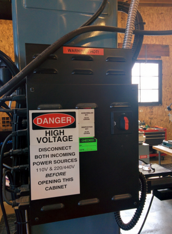
1. Turn on the rocker switch on the back of the control box.
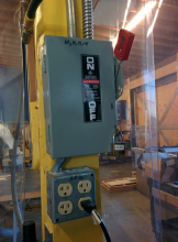
2. Turn on the main power at the wall switch.
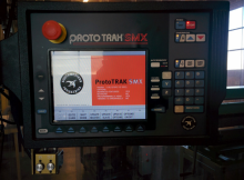
3. Using the “System” button, choose your preference of 2- or 3-axis operation.
Setup
First Tool Setup
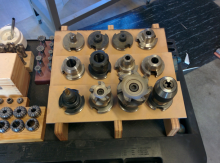
1. Pre-load all tools for your program in the tool holders as necessary.
2. Insert Tool 1 in the machine. Not any other tool. For this to work correctly, it has to be Tool 1 in your sequence.

3. Enter DRO mode via the “Menu” button. If you don’t see it, keep pressing the “Mode” button to get to the root menu.
4. To adjust the head up and down for tool installation, you will need to press the “Jog” button. Once this button is pressed, the mill is considered live, and therefore dangerous! Any time you hit any “x”, “y”, or”z” key, the mill will make a rapid move in that direction. There is a window at the lower left of the DRO screen that will tell you your “feed speed”. If it is a positive number, the mill will rapid in a positive direction. If it has a negative symbol, it will rapid in a negative direction. Know which direction the machine is going to travel before you touch a button, or you may crash the machine! To switch between positive and negative directions, use the “+/- “ symbol on the keypad. The feed speed will then switch between negative and positive. The negative will be represented by a “-“ sign in front of the number
5. Once the tool has been installed, “jog” the tool down to about 3 inches from your part, and stop. Immediately press the “Return” button to remove yourself from the jog screen!
6. Make sure at the top of the screen it says ”Tool 1”. If not, press the “Tool Number” button at the bottom, and enter the number “1” followed by the “Abs Set” button. Make sure it changes to “Tool 1”.
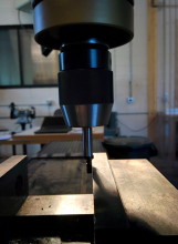
7. You should now be back on the “DRO” screen. While in the DRO screen, bring the tool down to touch the zero plane of your part using the hand quill.
8. Double check to make sure you are no longer in Jog mode. If you are still in Jog mode, there will be a red bar at the top of the screen.
9. With the tool tip at the “z” zero plane, press the “z” button followed by “0” and then the “Abs Set” button. Your z-axis should now read “0” on the DRO screen.
10. Without removing the current tool, press the “Setup” button available via the “Mode” button.
11. Press the “Tool Table” button. You are now in the Tool Table. Press the “Erase Table” button to clear all remaining tool information. Using the data up/down/left/right buttons, navigate your way to the very top of the list, and highlight the words “Not Set”. Using the hand quill, bring your tool back down to the same reference plane that you had it when setting the tool zero. Once there, press the “Abs Set” button. Your reference position is now set.
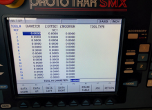
12. Navigate your way to the “Dia” column of Tool 1 in the list, and make sure it is highlighted. Enter the diameter of the tool using the keypad, and press the “Abs Set” button.
13. With the quill still in the lowered position, press the “Abs Set” key again to enter the “z offset”. It should read zero. If not, the tool moved from your reference location.
14. If you press the “Abs Set” key one more time, a menu will pop up in which you can enter the tool type. Choose the number that best represents your tool type, and press enter.
15. Press the “Return” button to get back to the setup menu, and then press the “Ref Posn” button. This creates a “safety location” for the spindle and table to go to for tool changes, and at the beginning and end of a program.
16. Fold in the handles on the x and y axes. Using the “jog” option at the bottom of the screen, jog your x, y, and z axes to a location high enough to easily clear any tools and parts. Be careful! You are in jog mode, so all the same rules apply from above. You can also move the x and y axes manually with the hand wheels if that is your preference. Once you have placed the tool in the safety location, press the “return” button to get back to the reference position screen.
17. Make sure “Ref Pos” is highlighted, and press the “Abs Set” button. Now your reference position has been set.
Remaining Tools Setup
1. Insert the next tool in the machine. If you have not completed the first tool setup above, go back and complete it.Otherwise a machine crash will occur!
2. Enter DRO mode via the “Menu” button. If you don’t see it, keep pressing the “Mode” button to get to the root menu.
3. To adjust the head up and down for tool installation, you will need to press the “Jog” button. Once this button is pressed, the mill is considered live, and therefore dangerous! Any time you hit any “x”, “y”, or ”z” key, the mill will make a rapid move in that direction. There is a window at the lower left of the DRO screen that will tell you your “feed speed”. If it is a positive number, the mill will rapid in a positive direction. If it has a negative symbol, it will rapid in a negative direction. Know which direction the machine is going to travel before you touch a button, or you may crash the machine! To switch between positive and negative directions, use the “+/- “ symbol on the key pad. The feed speed will then switch between negative and positive. The negative will be represented by a “-“ sign in front of the number.
4. Once the tool has been installed, “jog” the tool down to about 3 inches from your part, and stop. Immediately press the “return” button to remove yourself from the jog screen!
5. Double check to make sure you are no longer in “jog” mode. If you are still in jog mode, there will be a red bar at the top of the screen.
6. Without removing the current tool, press the “Setup” button available via the “Mode” button.
7. Press the “Tool Table” button. You are now in the Tool Table. Your reference position should already be set, as well as your info for Tool 1. If it is not, repeat the “first tool setup” instructions.
8. Using the data up/down/left/right buttons, navigate your way to the “Dis” column of the tool number that corresponds to the tool that is currently in the spindle, and make sure it is highlighted. Enter the diameter of the tool using the keypad, and press the “Abs Set” button. Now the “Offset” column should be highlighted. Using the hand quill, bring the tool down to the same reference plane that you set Tool 1 to. Once there, press the “make sure it is highlighted. Enter the diameter of the tool using the keypad, and press the “Abs Set” button.
9. Now a menu will pop up in which you can enter the “Tool Type”. Choose the number that best represents your tool type, and press enter.
10. You have just set up any tool besides Tool 1. Repeat this process for any remaining tools.
Setting Your Origin
1. Complete all steps above completely.
2. Using the “Mode” button, navigate to the “DRO” page.
3. Using the handwheels, locate the “x” and “y” axes to the location you would like your origin to be.
4. Double check to make sure you are no longer in “jog” mode. If you are still in jog mode, there will be a red bar at the top of the screen.
5. Press the “x” or “y” button followed by the “Abs Set” key to zero that axis. Repeat for the remaining axis.
6. Do not change the “z” axis setting!!!!!! If you did accidentally, repeat the “first tool setup” instructions.
7. If you are using an edge finder, you will need to press the “Spin Speed” button, and enter the rpm you wish the spindle to turn at (less than 600 rpm for all edge finders).

Then press the “Abs Set” key. Now when you turn on the spindle, the speed will adjust automatically to your requested speed. When you get the edge finder to “run” perpendicular to an axis, you need to enter your actual location in that axis. In other words, using an edge finder with a 0.2 inch diameter tip on the left side of a part when facing the front of the machine would require the input of “ -.1 Inches” (the radius of a 0.2” tool) in the x- axis. Press the “x” or “y” button representing your current location, and enter the position.
Then press the “Abs Set” key to set that axis. Repeat for the remaining axis.
8. Double check your origin by moving to (x0, y0), and look at the tool relative to your part.
9. You have now set your origin.