MPU-6050 Six-Axis (Gyro + Accelerometer) MEMS MotionTracking Device (datasheet)
(nice tutorial http://www.geeetech.com/wiki/index.php/MPU-6050_Triple_Axis_Accelerometer_%26_Gyro_Breakout)
Hardware Setup
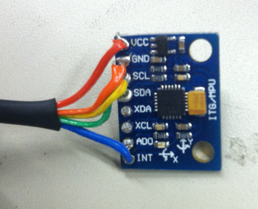
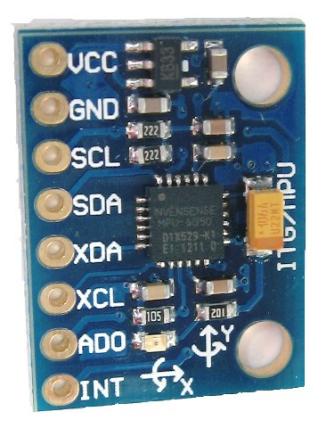
Pin Connections
| MPU6050 | Arduino UNO or FIO |
|---|---|
| VCC | 3.3V |
| GND | GND |
| SDA | A4 |
| SCL | A5 |
| INT | Pin 2 (interrupt #0) |
NOTE: This is a 3.3V device. If using the Arduino UNO or other 5V platform, be sure to power the MPU6050 breakout from the low voltage (3.3V) line. The SDA and SCL inputs will be fine, you do not need to worry about them.

THIS IS HORRIBLE SOLDERING (AND A BLURRY PHOTO)! YOU CAN DO BETTER!
Code
You need two pieces of code here: one arduino program that handles the actual I2C communication with the MPU6050 device and a processing sketch that interprets the data.
- Arduino program twomey_MPU6050_DMP6.zip
- handles initialization of device, storing home position, and writing position/orientation data to the serial port.
- Processing sketch FreeIMU_cube.zip
- receives data from arduino and displays it onscreen.
- additional functionality to store a home orientation for device, which enables calibration.
- this code also streams the data to a given OSC address. you can use to communicate with SuperCollider or some other language.
