EagleCad tutorial part 2: layout board
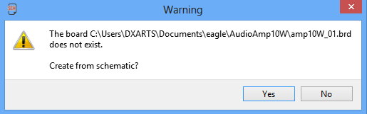
1. In schematic windows, go to File > Switch to board. Click 'Yes' to create the board view
The board view window will open:
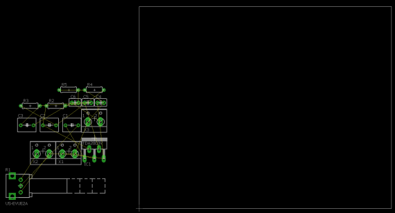
2. We must first move our components onto the board. Click on ![]()
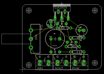
3. Arrange the components in a way that makes sense on the board. In this example we need our screw terminals accessible, so they need to face out. Components can be rotated by left clicking on the ![]()
4. Resize the board. Click on the corners of the white rectangle and move to resize the board. To add mouting hole, select ![]()
5. Next, we will use AutoRouter function. Click on ![]()
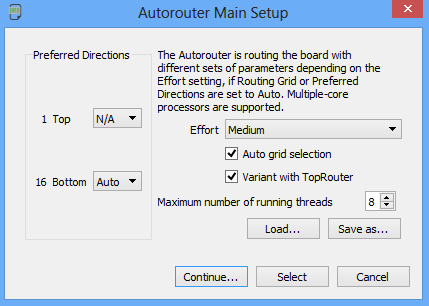
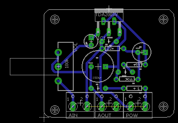
On the next window, click Start and wait for the process to finish. If auto router finish, you should see ![]()