Overview
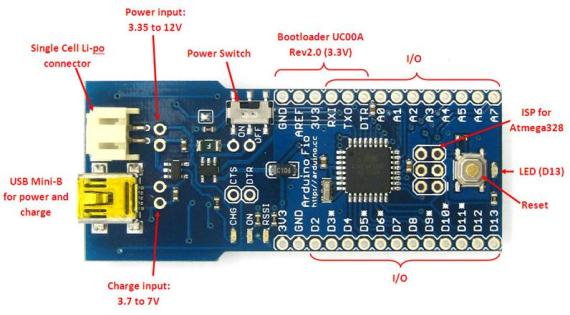
The Arduino Fio is a microcontroller board based on the ATmega328P (datasheet) runs at 3.3V and 8 MHz. It has 14 digital input/output pins (of which 6 can be used as PWM outputs), 8 analog inputs, an on-board resonator, a reset button, and holes for mounting pin headers. It has connections for a Lithium Polymer battery and includes a charge circuit over USB. An XBee socket is available on the bottom of the board.
The Arduino Fio is intended for wireless applications. The user can upload sketches with an a FTDI cable or Sparkfun breakout board. Additionally, by using a modified USB-to-XBee adaptor such as XBee Explorer USB, the user can upload sketches wirelessly. The board comes without pre-mounted headers, allowing the use of various types of connectors or direct soldering of wires.
The Arduino Fio was designed by Shigeru Kobayashi and SparkFun Electronics, and manufactured by SparkFun Electronics.
(source: Arduino FIO reference page)
Initial Setup
Solder FTDI Pin Headers
- You need six pins to connect the FTDI cable and program the FIO.
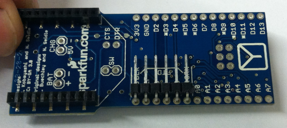
- One approach is to attach 0.1" male right-angle headers (6 position) on the underside of the board.
- Attach the pins to the labelled FTDI area on underside of board, with pins pointed inwards.
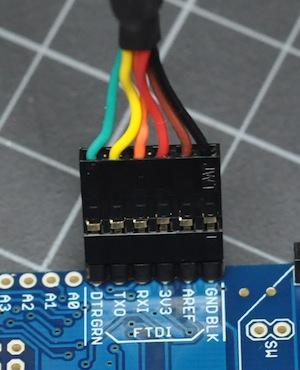
- This is where you will attach the USB-to-TTL cable to program the board:
Input/Output Pins
- Approach 1. Permanent Soldered Connections:
- Soldered Solder connections to sensors, inputs, outputs AS NECESSARY. Be careful soldering and desoldering so as not to destroy the board. This is your most permanent attachment solution.
- Good for permanent installation of the FIO, applications with lots of motion, wearable devices.
- Approach 2. Screw Terminals:
- Solder screw terminals to inputs and outputs as needed. These will give you strong but flexible (reusable) input and output connections.
- Pins can be repurposed at a later point.
- Screw terminals will secure peripherals in a semi-permanent manner.
- Approach 3: Arduino Standard
- Solder on the typical arduino single-row female headers to the top side of the board.
- This will give you flexibility for prototyping with less permanent connections than the previous options.
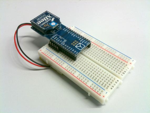
- You can stack "shield" type protoboards on the xbee with this setup.
- With male single-row headers in a breadboard, you can use the fio for breadboarding:
Using the TTL Cable
Wired Programming
- Remove the XBee module if you have one attached to the FIO. The Xbee and the serial adapter share the same TX/RX pins. THey will interfere with each other. You can reconnect the xbee when you are done uploading a program.
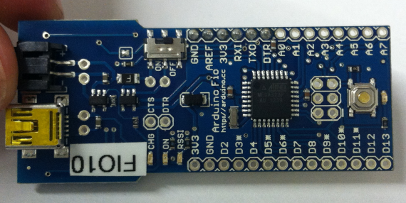
- Connect a 3.3V FTDI cable to the correct pins on the Xbee. Be sure to match colors as described on the underside of the board:
- The FTDI cable will power the FIO (3V3 and GND) from the USB port, as well as communicate with the device. You do not need the battery pack or mini-USB charging cable attached.
- Upload a simple Blink (or meaningful blink) program. When done uploading, you should see it execute on the bright red led on the bottom of the FIO board.
- Disconnect the FTDI cable and power the device from the LiPO battery pack. Does the blinking still work?
Wired Operation
- With the FIO connected to the FTDI cable, you can use the FIO just like a normal arduino.
- Data well be sent and received over the TX and RX pins, and show up on the computer through the serial port.
- All the same input/output circuits, low-high current interface concerns are present.
- NOTE: The FIO is a 3.3V device (not 5V like the UNO). This changes values for any resistors in voltage divider circuits, LED outputs, as well as affecting how you use any powered peripherals (like IR range finders).
Using FIO and XBee Radios
Configuring the Xbee modules
- Use an Xbee explorer or USB Xbee Adapter to configure individual xbee radios.
- You need to set the network ID (ATID), device address (ATMY), and destination address (ATDL).
- The combination of ATMY and ATDL settings on your local network determine the topology.
- Follow the Xbee Tutorial.
Arduino to Computer
Arduino to Arduino
Computer to Computer
- You could, but when would you want to? There are many other ways to do this.
- Raspberry Pi -> Raspberry Pi.
Battery Power
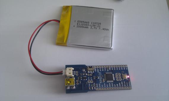
- A variety of Lithium Polymer battery packs are compatible with the Arduino FIO.
- Simple plug in the JST connector:
- The JST connectors are quite tight, and may be difficult to remove. Get help from your TA or Professor if you are stuck.
Battery Charging
- The FIO has a dedicated battery charging chip. It takes 5V power from the mini-USB jack and charges the 3.7/3.3V LiPO battery. There are also exposed Charge input pads (labelled in the diagram at top) if you wish to connect some other sort of DC power supply.
- NOTE: The mini-USB does not work for programming the FIO or serial communication! It just provides power.
- The FIO has a charging indicator light (CHG) that shows you the device is charging. Batteries take approx 1 hour to charge (M.Trainor).